Mechanical Parts
Diesel Generator Engine
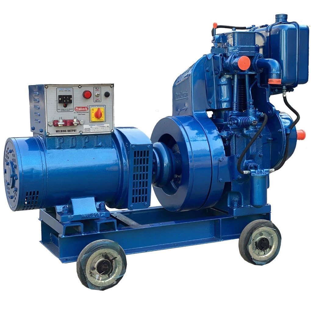
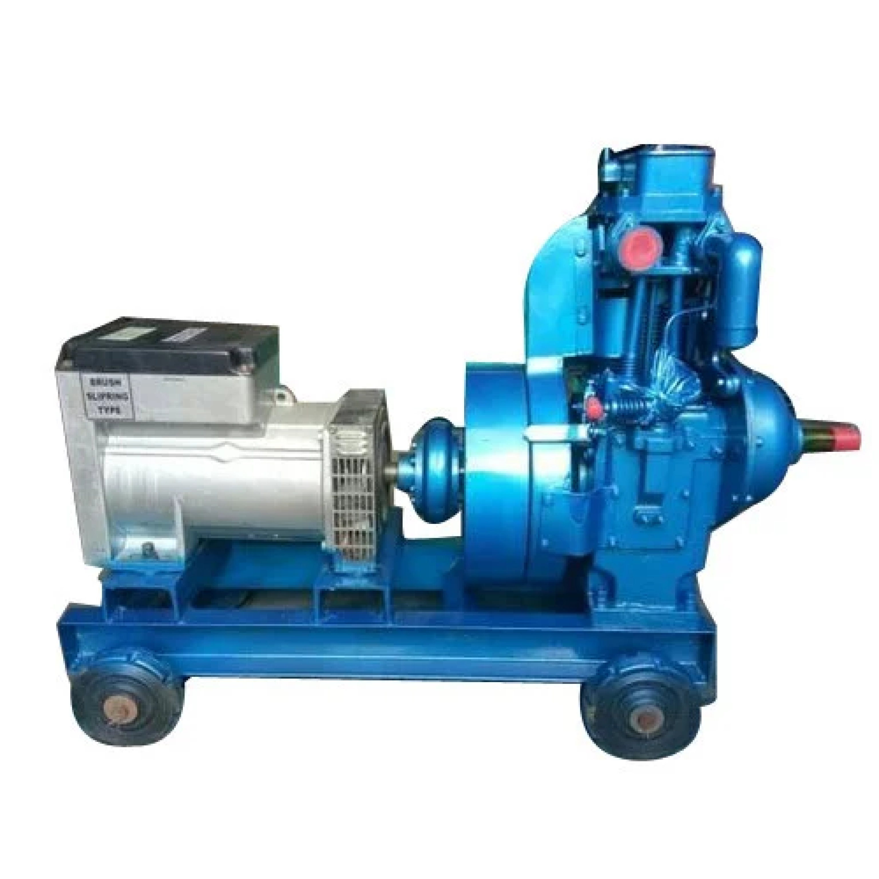
A diesel generator engine is a type of internal combustion engine that is specifically designed to drive an electrical generator to produce electricity. It operates on diesel fuel, which is ignited within the engine to generate power. Diesel generator engines are widely used as a backup power source in various settings, including industrial facilities, commercial buildings, hospitals, data centers, and residential properties. Diesel generator engines are valued for their reliability, durability, and ability to provide continuous power for extended periods. They are often used as a backup power source during grid outages or in remote locations where access to the electrical grid is limited.
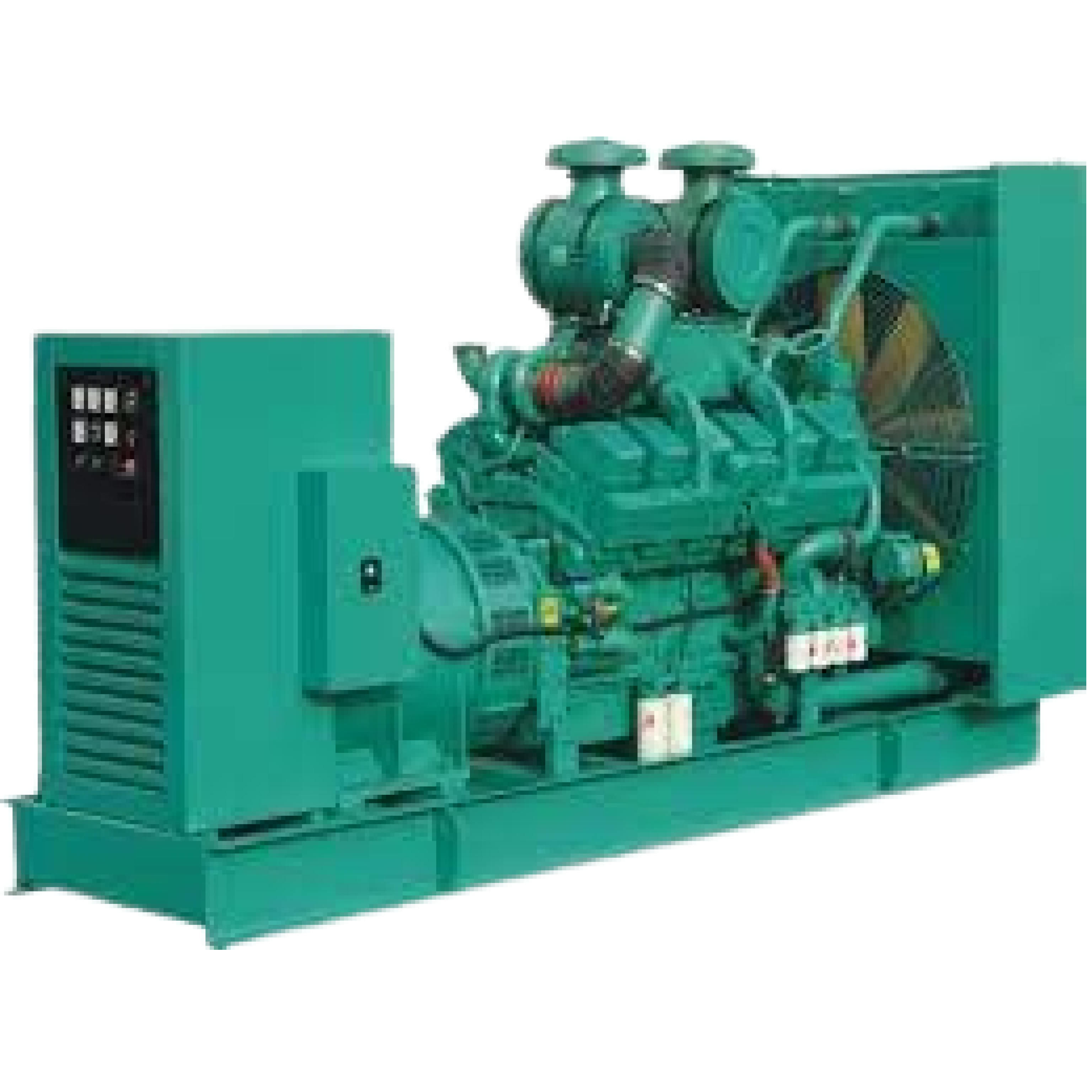
Additionally, diesel generator engines are available in a wide range of sizes, from small portable units to large industrial generators, making them suitable for various applications. Key components of a diesel generator engine include:
1. Diesel Engine: The core of the generator, the diesel engine is responsible for converting the chemical energy stored in diesel fuel into mechanical energy. This mechanical energy is then used to turn the generator’s rotor, which produces electrical power.
2. Generator: The generator is driven by the diesel engine and converts the mechanical energy into electrical energy. It typically consists of a rotor and a stator, where the relative motion between the two components induces an electrical current.
3. Fuel System: The fuel system supplies diesel fuel to the engine, where it is atomized and mixed with air before being ignited. The system includes components such as fuel tanks, fuel pumps, injectors, and filters.
4. Cooling System: Diesel generator engines require cooling to dissipate the heat generated during operation. This system typically includes a radiator, cooling fan, and coolant circulation system to maintain optimal operating temperatures.
5. Exhaust System: The exhaust system is responsible for removing the combustion gases from the engine. It includes components such as exhaust manifolds, mufflers, and exhaust pipes.
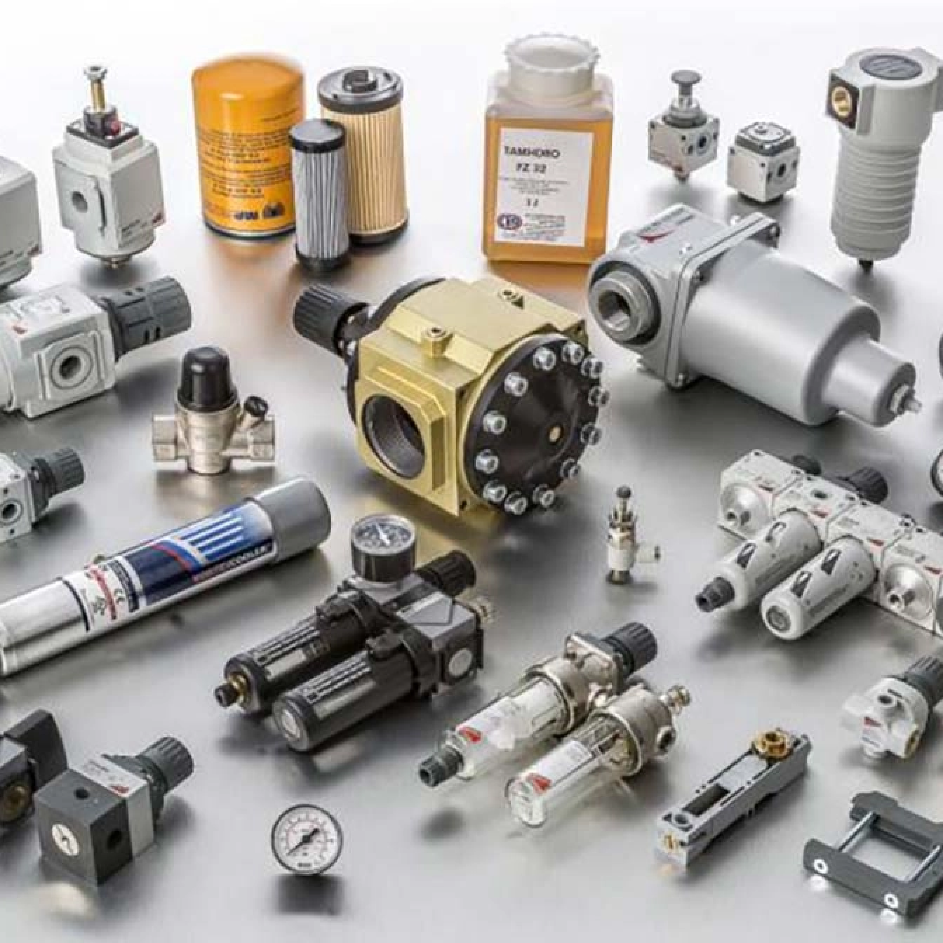
Air Compressor and Parts
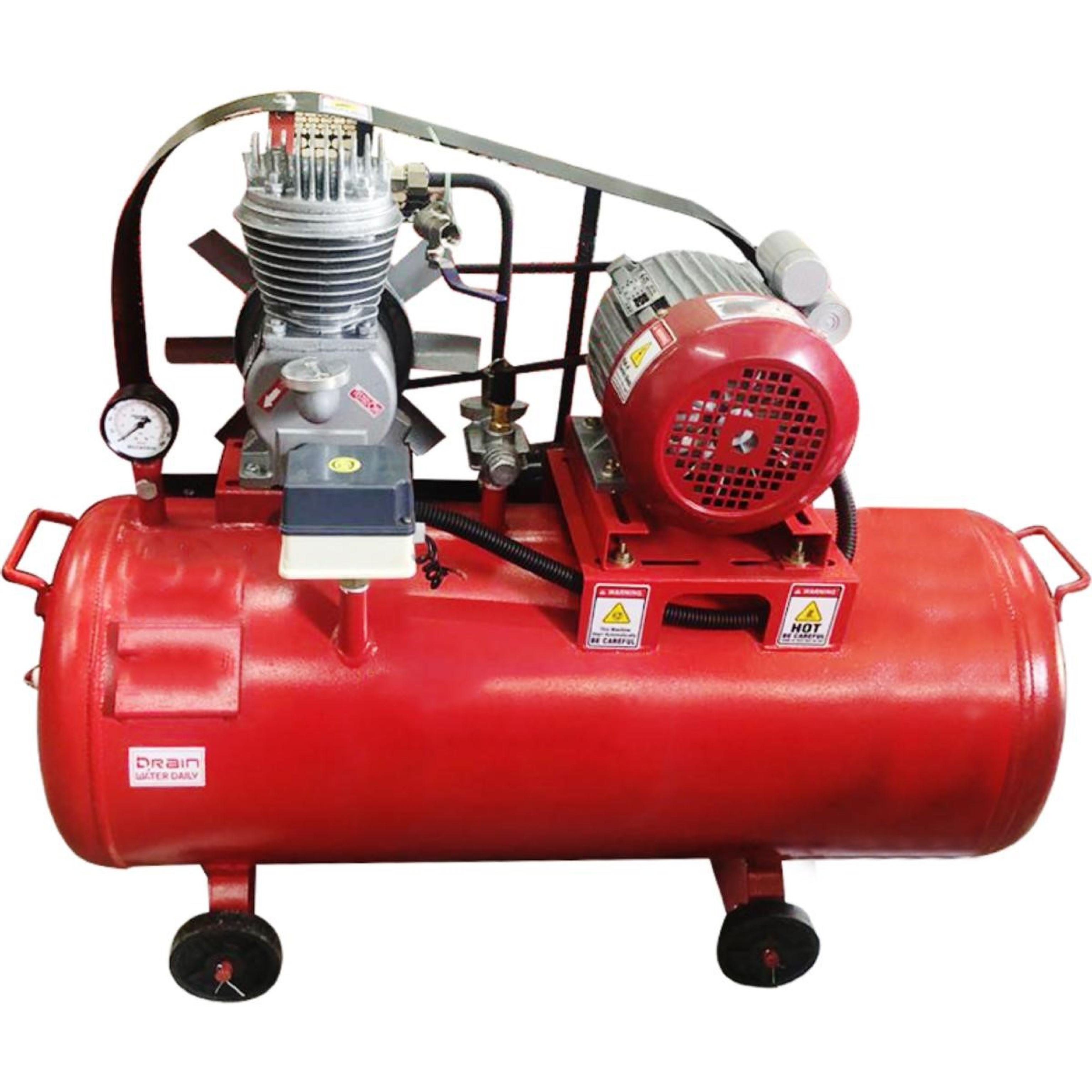
An air compressor is a device that converts power into potential energy stored in pressurized air. This compressed air can then be used for various applications, such as powering pneumatic tools, inflating tires, and even in industrial processes. There are different types of air compressors, including reciprocating, rotary screw, and centrifugal compressors, each with its own unique design and functionality. Air compressors are commonly used in workshops, construction sites, manufacturing facilities, and automotive repair shops.
The main components of an air compressor include the pump, motor, tank, pressure switch, pressure gauge, safety valve, and various other fittings and controls. These components work together to compress and store air, and then deliver it to the desired location for use. Air compressors come in various sizes and capacities, ranging from small portable units for home use to large industrial-grade systems. They are essential tools in many industries and are used for a wide range of applications.

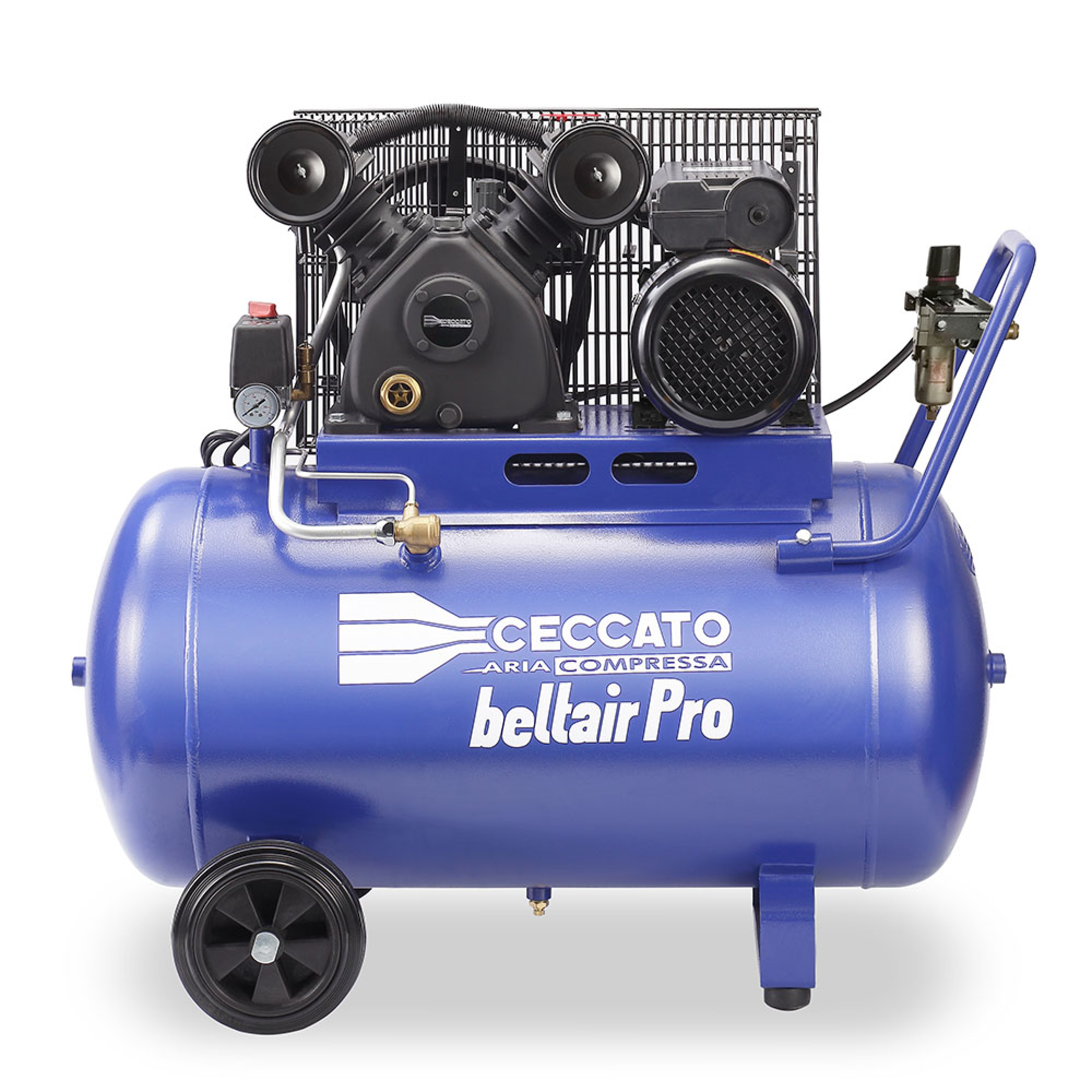
Different parts of Air compressor:
1. Air compressor pump – the main component that pressurizes and moves air.
2. Pressure switch – controls the on/off function of the compressor.
3. Air filter – removes impurities and contaminants from the air.
4. Pressure gauge – measures the air pressure in the compressor tank.
5. Safety valve – releases excess pressure to prevent tank rupture.
6. Motor – provides power to the compressor pump.
7. Tank – stores compressed air for use.
8. Regulator – controls the air pressure output.
9. Hose and fittings – connect the compressor to tools or other equipment.
10. Drain valve – allows for the release of moisture from the tank.
Steam Boiler and Parts
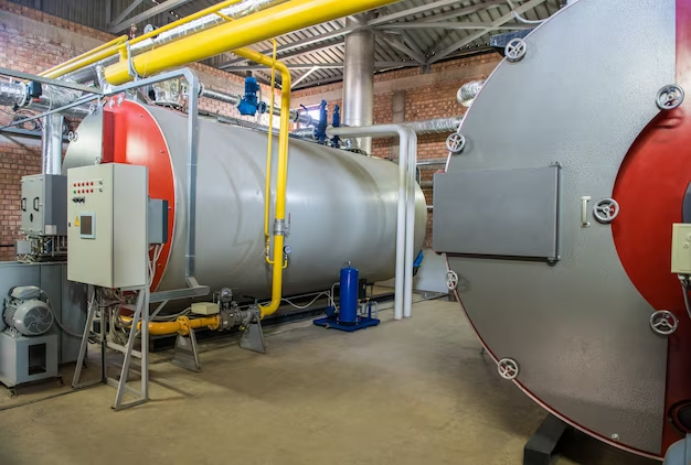
A steam boiler is a device used to create steam by heating water to generate energy. This steam is then used for various purposes, such as powering machinery, heating buildings, or providing hot water. Steam boilers are commonly found in industrial and commercial settings, as well as in some residential applications. The basic components of a steam boiler include a vessel for holding water, a heat source (such as a burner or electric heating elements), a system for transferring heat to the water, and a mechanism for releasing the generated steam. The process typically involves heating the water to its boiling point to produce steam, which is then directed to the desired location for use.
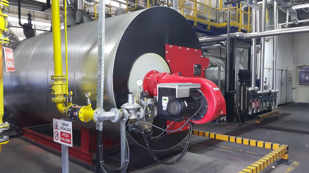
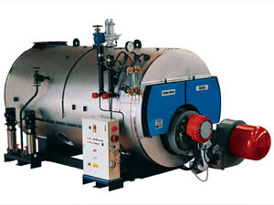
There are different types of steam boilers, including fire-tube boilers, water-tube boilers, and electric boilers, each with its own unique design and functionality. The choice of boiler type depends on factors such as the intended application, required steam capacity, and fuel source. Steam boilers are widely used in industries such as power generation, manufacturing, food processing, and chemical production. They are essential for providing the energy needed for various industrial processes and are a key component of many industrial operations. These are the essential components of a steam boiler, and there are additional parts and accessories depending on the specific design and application of the boiler.
The main parts of a steam boiler include:
1. Boiler shell: The outer vessel that contains the water and steam.
2. Water level indicator: A device to show the water level inside the boiler.
3. Burner: The component that provides the heat source to boil the water and produce steam.
4. Heat exchanger: The part that transfers heat from the burner to the water to create steam.
5. Safety valve: A critical safety device that releases excess pressure to prevent the boiler from exploding.
6. Pressure gauge: A device used to monitor the pressure inside the boiler.
7. Steam outlet: The point where the generated steam is released for use.
8. Control panel: The interface for operating and regulating the boiler’s functions.
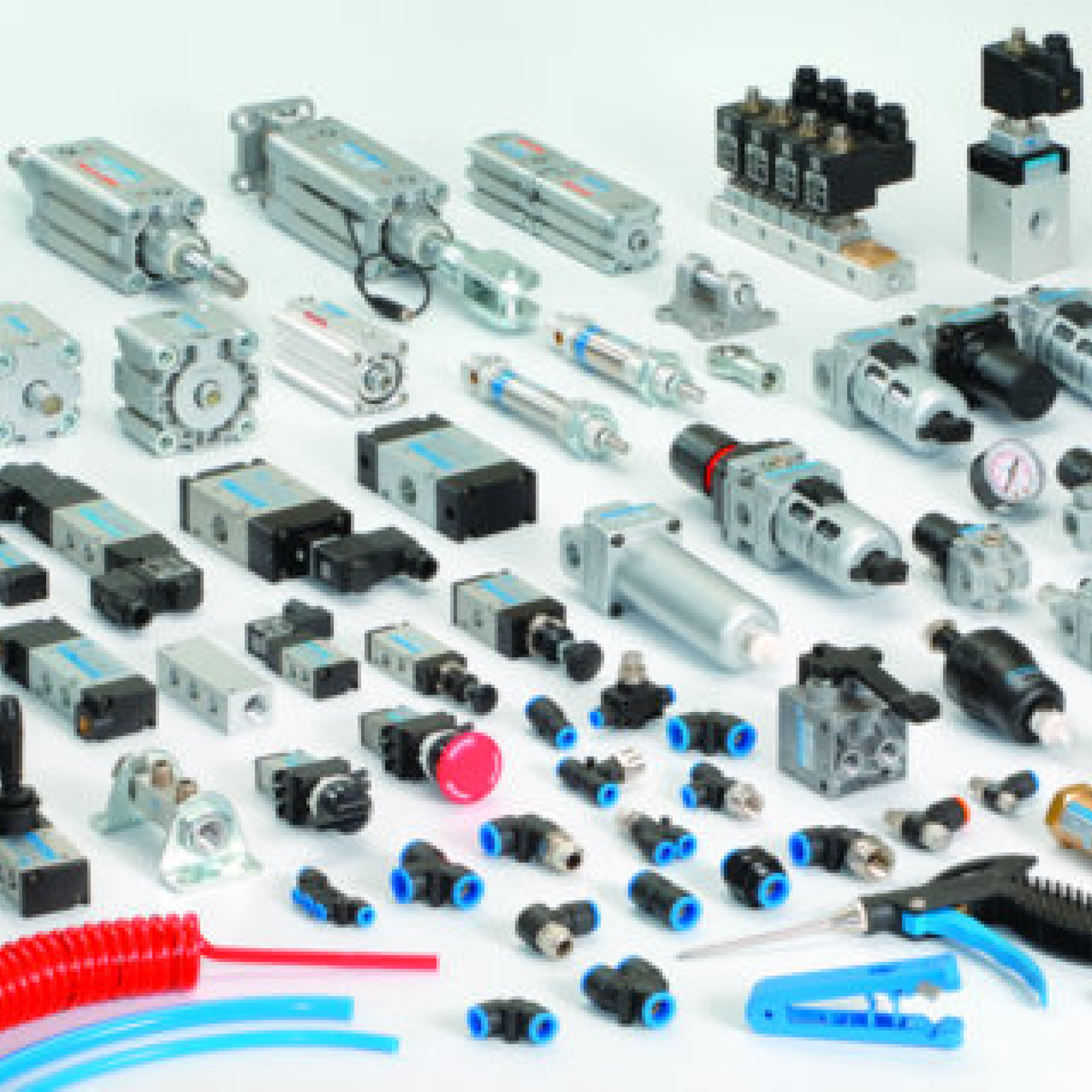
Pneumatic Spares
Pneumatic spares refer to replacement parts and components used in pneumatic systems, which are systems that use compressed air to transmit and control energy. Some common pneumatic spares include:
1. Pneumatic cylinders: These are devices that use the force of compressed air to produce linear motion.
2. Pneumatic valves: These control the flow of compressed air in a pneumatic system, regulating the direction, flow rate, and pressure.
3. Pneumatic fittings: These are connectors used to join sections of pneumatic tubing or hose together.
4. Air filters and regulators: These components are used to ensure that the compressed air is clean and at the correct pressure for the pneumatic system.
5. Pneumatic hoses and tubing: These are used to transport the compressed air from the source to the pneumatic components.
6. Pneumatic actuators: These are devices that convert the energy from compressed air into mechanical motion.
7. Pneumatic control panels and accessories: These include various control devices, gauges, and indicators used to monitor and regulate pneumatic systems.
These are just a few examples of pneumatic spares, and there are many other components and parts that may be considered pneumatic spares depending on the specific needs of a pneumatic system.
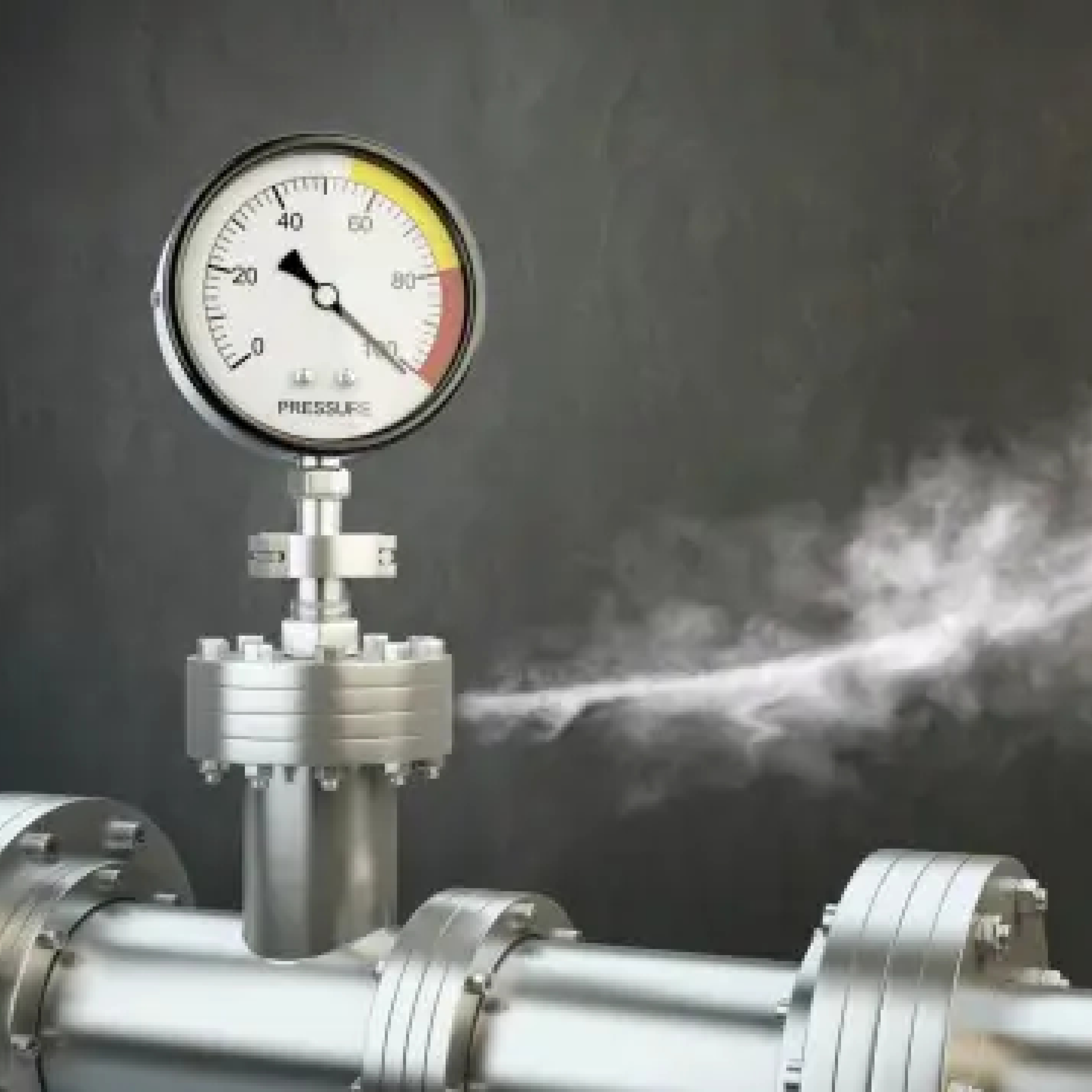
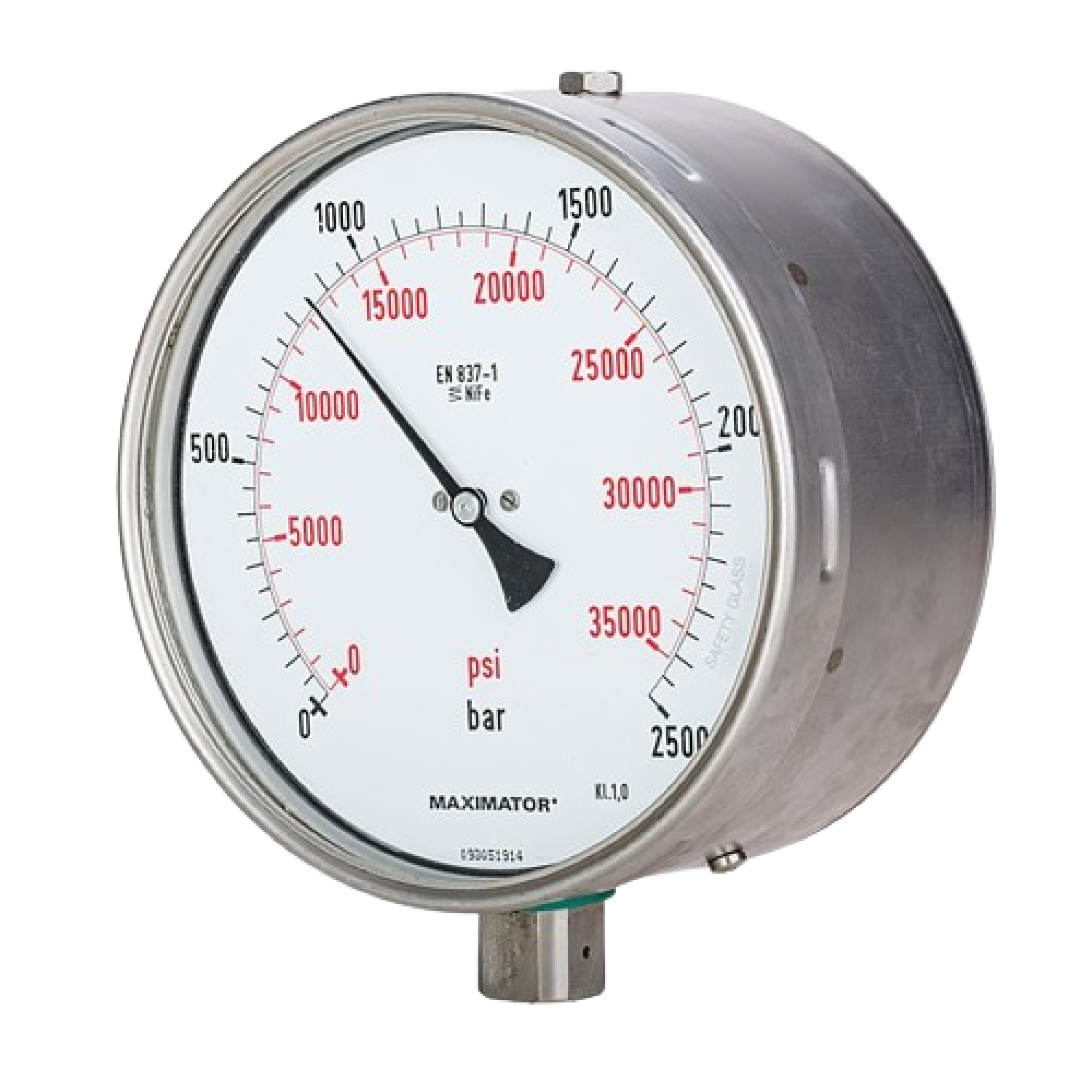
Pressure Gauge
A pressure gauge is a device used to measure the pressure of a gas or liquid within a system. Pressure gauges are commonly used in various applications, including industrial machinery, pneumatic systems, hydraulic systems, and HVAC systems. Pressure gauges come in various types and designs to suit different pressure ranges, fluid types, and environmental conditions. They are essential for monitoring and maintaining safe and efficient operation of many mechanical systems. The main components of a pressure gauge typically include:
1. Dial face: The display that shows the pressure reading, usually marked with units such as psi (pounds per square inch) or bar.
2. Bourdon tube: A curved tube within the pressure gauge that deforms in response to changes in pressure, which is then translated into a pressure reading on the dial face.
3. Pointer: The hand on the dial face that indicates the pressure reading.
4. Case: The housing that encloses the internal components of the pressure gauge, protecting them from damage and environmental factors.
5. Connection port: The point where the pressure gauge is connected to the system or equipment to measure the pressure.

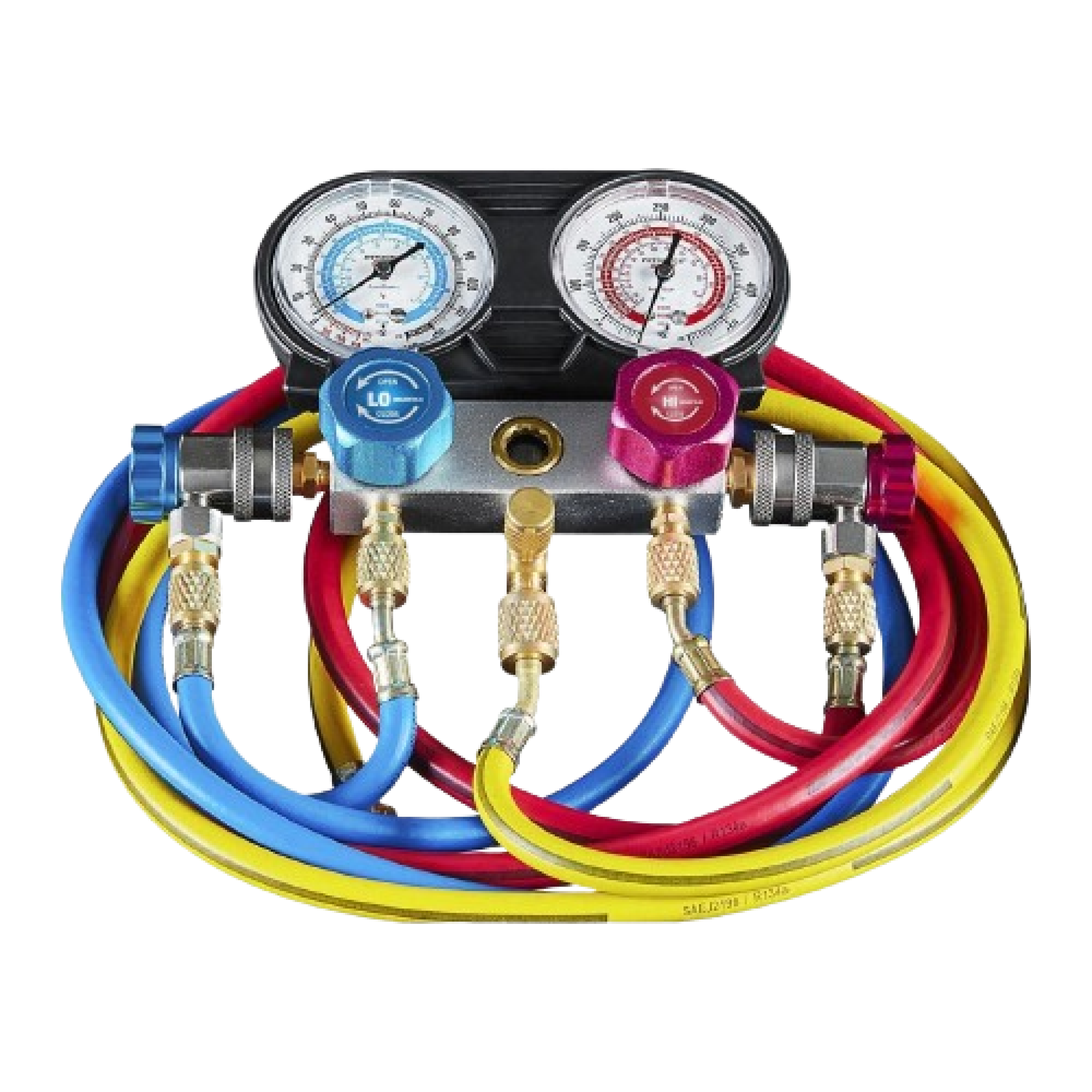
Manifold Gauge
A manifold gauge, often used in refrigeration and air conditioning systems, is a tool that consists of a set of gauges and valves designed to measure pressure and regulate the flow of refrigerant. It is commonly used by HVAC technicians and refrigeration mechanics to diagnose and service cooling systems. Manifold gauges are used to measure system pressures, check for leaks, and add or remove refrigerant from the system. They provide essential information for diagnosing and troubleshooting problems with refrigeration and air conditioning systems.
The main components of a manifold gauge set typically include:
1. Gauges: A manifold gauge set usually includes two gauges, one for high-pressure and one for low-pressure readings. These gauges display the pressure of the refrigerant within the system.
2. Hoses: The gauges are connected to the refrigeration system via hoses, which allow the technician to measure the pressure and transfer the refrigerant.
3. Valves: The manifold gauge set includes valves that allow the technician to open and close the connections to the system, control the flow of refrigerant, and regulate the pressure within the hoses.